
Warum solch ein ausführlicher Artikel über das ATR-60-8
Das analoge 8-Spur Bandgerät war 1986 eines der letzten analogen Spulen- Bandgeräte - somit ein Meilenstein -, das weltweit überhaupt noch hergestellt und in Europa vertrieben wurde. Die damalige PCM-Technik von 1979 (Audio- Studio-Qualität über PCM-Converter aufgenommen auf hochwertige Videorecorder) war am Auslaufen, weil sie viel zu anfällig war (und eine Macke hatte). Die SONY-DAT- Kassetten-Technik kam erst ein paar Jahre später (etwa 1986/89), aber die großen digitalen 24-Kanal (DASH-) Bandrecorder auf 2" Spulen und auch die kleineren mit 8 Kanälen auf kleinen 8-mm Kassetten waren auf dem Vormarsch.
Dennoch behaupten ein paar - eigentlich als erfahren bekannte - Tonmeister, die professionellen analogen Aufnahmen überträfen "vom Höreindruck" jede digitale Aufnahme. Wie gesagt, wir sprechen vom Höreindruck, nicht von der absoluten physikalisch meßbaren Qualität.
Und darum schaun wir uns erst mal die Daten ganz unten auf dieser Seite an. Die Bandmaschine kann bei 38cm/s einen Frequenzgang von etwa 40Hz - 22kHz, ±2dB bei 0 "VU", also bei meßtechnischer Vollaussteuerung, wiedergeben. Der Rauschabstand bei der "nackten" Maschine liegt bei ca. 67db (20 - 20 kHz), ist aber ganz bestimmt vom optimalen Bandmaterial abhängig. Natürlich haben die Entwickler in Japan für solche Messungen das beste Band genommen, das sie damals finden konnten.
Auch haben sie bei den Rauschunterdrückern sicher die DOLBY Varianten und die dbx Varianten verglichen und sich für das professionelle dbx entschieden. Das bringt angeblich weitere 30db Rauschabstand. Und somit hätten sie meßtechnisch :
Ein Rauschabstand von theoretisch 97db ????
.
SECTION I. GENERAL INFORMATION
(Unser Stand dieses Ordners ist vermutlich vom Ende Juni und Augst 1986.)
.
1.1 INTRODUCTION

This manual includes information for the operation and maintenance of two different professional tape machines: the 4-track ATR-60-4HS (Audio Tape Recorder, Series 60, 4-track, High Speed), and the 8-track ATR-60-8.
NOTE: Rather than repeatedly use the phrase "ATR-60-4HS and ATR-60-8" when refering to both models, we may use the abbreviation "ATR-60-4/8" or "ATR-60-4 and -8". There is no difference in meaning; we just want to make this manual shorter and easier to read.
ATR-60-4HS

1/4 Track NAB 4-Track head format, 1/2" wide tape at 15 ips or 30 ips (38 cm/sec or 76 cm/sec), EQ set for I EC @ 15 ips (switch-able NAB) or AES @ 30 ips, fluxivity set for 320 nWb/m (switchable 250 nWb/m).
ATR-60-8
1/8 Track IEC 8-Track head format, 1/2" wide tape at 7,5 ips or 15 ips (19 cm/sec or 38 cm/sec), EQ set for IEC (switchable NAB), fluxivity set for 250 nWb/m (switchable 320 nWb/m).
Aufbau der Geräte
Each model is built with the transport in one chassis, and the electronics in another. This modular design enables the tape transport and electronics to be mounted in a standard 19" wide EIA equipment rack, in a portable 19" rack case, in a roll-around console such as the TASCAM CS-65 with CS-62 overbridge kit that places the electronics in an overbridge configuration, or in a custom console.
The TASCAM RC-65 Remote Transport Control unit may be used with either of the ATR-60-4 or -8 models, providing a convenient "long arm" to operate all transport functions, including pitch control.
For even greater flexibility, the TASCAM AQ-65 Multi-Function Auto Locator can be connected, which provides 10 cue point memory, programmable pre-roll, and two-point repeat.
Das ATR60 Laufwerk
The ATR-60-4/8 transport is an exceptionally reliable, professional design. It is built on an extra heavy duty chassis that assures stable alignment and the utmost accuracy in tape motion. The hefty construction of the transport also minimizes maintenance.
The microprocessor ensures smooth, fast, and accurate tape motion by commanding a pair of direct drive reel motors and a Phase Lock Loop servo capstan motor. Even in synchronized lock-up to other audio transports, film chains or video systems, the ATR-60-4/8 has plenty of torque and accuracy to keep in step with a busy work schedule.
What's more, this transport's physical and electronic stability minimizes stretch and wear on recording tape during long hours of high speed, start-stop shuttling.
Time-Code Information
Interface between the ATR-60-4/8 and any time code based equipment (synchronizer, resolver, etc) is accomplished via a single, rear panel "Accessory" connector.
This connector carries all the necessary logic and tally signals for use with Adams-Smith, Audio Kinetics, Cypher Digital, Convergence, EECO, TimeLine, United Media, Video Media and other similar systems.
.
Der Elektronik-Teil
The ATR-60-4/8 electronics are mounted on plug-in, printed circuit boards for ease of service. The VU meter panel swings out and down for immediate access to all the trimmers required for routine alignment.
This method also makes it easy to observe the VU meters while making adjustments, and alignment is equally easy whether the unit is vertically or horizontally mounted.
1.2 THE TAPE TRANSPORT
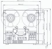
- FIGURE 2-1. ATR-60-4/8 TRANSPORT AND AMPLIFIER DIMENSIONS

The main transport components are all mounted on a rigid, precision-machined aluminum base plate. This provides an exceptionally stable platform for the supply and takeup reel motors, capstan motor, impedance roller, pinch roller, tachometer roller, digital counter, tape tension arms and guide rollers. A stable platform is essential for smooth, stable tape motion, but alone does not assure good tape handling.
microprocessor controlled
In order to handle tape in the best possible manner, the ATR-60-4/8 transport is fully microprocessor controlled, including fast forward, rewind, play, and spooling modes. The microprocessor (uP) is specifically programmed for this series of transports (refer to Figure 1-2 for a block diagram of uP functions) to further optimize tape motion.
A full servo reel system keeps tape tension within carefully regulated limits to avoid stretching. The capstan motor is strictly regulated by a phase-lock loop (PLL) servo system. The capstan motor's large size, brushless DC design, and ceramic direct-drive capstan shaft all work together to minimize cogging and other speed variations while providing extended service life.
Die Bandzugsregelung
The tension servo employs a "non-contacting" detector that utilizes the principle of mutual inductance to sense the actual tape tension. There are two coils on either side of an aluminum plate that moves in and out of a field between the coils in proportion to tension arm position. This approach is more stable, and less prone to aging effects than is the more common LED/LDR arrangement (and is vastly better than mechanical rheostat-based systems).
Major rotating components, including the tension arm guides and the pinch roller, are supported by ball bearings to provide minimum friction while retaining close tolerances. In fact, the tension arm itself is ball-bearing supported for more sensitive response and greater durability.
Der Tachometer
The tachometer roller measures linear tape footage. The readout, however, is converted to elapsed time from whatever zero point is entered into memory. As the tape moves, it drives the tacho roller, causing a radially marked disk on the roller shaft to interrupt a photo sensor, which drives the digital counter circuitry. A thin rubber coating on the tach roller prevents tape slippage (for the most accurate results), and also protects the surface of the tape.
1.3 THE HEAD ASSEMBLY (Kopfträger)

The head assembly includes two fixed guides, a scrape flutter filter (idler roller) and three heads: erase, record/sync and reproduce (repro). A flip-up cover and a latching, push-down head shield (gate) provide full access to the heads for cleaning and editing.
Both the record/sync head and the repro head yield the same high-quality, full frequency range reproduction upon playback. Because no quality is sacrificed by synchronous reproduction from the record/sync head, artistic performance judgements and mixing decisions which are made during an overdub or insert will be based upon the correct frequency balance and phase response — something not always true on machines with inferior sync reproduction, or if the sync head output must be specially equalized.
Der Tape-Lifter
A solenoid-actuated tape lifter automatically pushes the tape away from the heads during any of the fast winding modes (fast forward, rewind or spooling). This prevents unnecessary wear on the heads and tape, and the disturbing, loud, high-frequency sound that might otherwise damage monitor speakers. For added protection, the ATR-60-4/8 line outputs are also electronically muted. However, for editing, progressive engagement of the cue lever defeats the tape lifter so cues can be monitored while fast winding.
1.4 THE ELECTRONICS

The ATR-60-4 and -8 feature direct-coupled amplifiers for low distortion and optimum low frequency response. The first stage of the reproduce amplifier consists of a pair of very-low noise FETs (field effect transistors).
This differential amplifier eliminates the need to insert a coupling capacitor between the heads and the first stage amp; instead, the direct coupled servo amplifier brings the DC offset voltage to zero. The result is a smoother, wider frequency response with better transient and phase characteristics.
Alles auf Steckkarten
The amplifier section is constructed on plug-in printed circuit boards. Connections between boards are made via the mother board.
Just four front panel screws need to be removed to slide out the meter panel for electronic adjustments. The usual bias, audio level and EQ trimmers for both standards are provided, including separate controls for the SYNC and REPRO playback.
IEC Entzerrung (NAB ??)
The ATR-60-4HS automatically operates with IEC standard equalization at 15ips, and AES standard equalization at 30 ips.
The ATR-60-8 operates with IEC equalization at both speeds. Selection of 250 nWb/m or 320 nWb/m reference fluxivity levels on the ATR-60-4HS or ATR-60-8 is a matter of moving switches on the mother PC board. All trimmers are metal glazed for better mechanical durability, and to reduce susceptibility to value changes or deterioration induced by aging or the environment.
Der bias oscillator
The ATR-60-4 and -8 are equipped with a master bias oscillator, plus a separate bias amplifier for each track. This extra circuitry avoids track interaction via the bias circuit for quieter punch-in and punch-out, while establishing phase matched bias signals which avoid beating.
Große VU-Meters
Audio levels can be monitored on large VU meters which include peak indicating LEDs. The VU meters provide a familiar "average" level reference, while the peak LEDs respond to brief transients that often are not accurately portrayed by the meters. The operator is thus able to avoid unwanted distortion (tape saturation) without being overly conservative and sacrificing too much average level (hence achieving the optimum signal-to-noise performance consistent with the lowest possible distortion).
1.5 THE POWER SUPPLY
The power supply for the transport motors, logic and record/reproduce electronics is housed in the same chassis with the transport. An "umbilical" cable conveys power to the electronics module. The ATR-4/8 power transformer is factory set for one of several possible line voltages prior to shipment, in accordance with the country where the equipment is to be sold.
The factory adheres to the following standards:
- European models: 220 V, 50 Hz.
- U.K./Australian models: 240 V, 50 Hz.
- U.S.A./Canadian models: 120 V, 60 Hz.
- General Export models: 100/120/220/240 V, (switchable voltage) 50 or 60 Hz.
.
Die einzelnen Sekundär-Spannungen
The following supply voltages are available to the transport and audio electronics:
- (1) Regulated, bipolar 15 volt DC for audio amplifiers. This supply includes an exclusive tracking filter circuit to eliminate AC ripple.
- (2) Regulated bipolar 20 volt DC for the operational status indicators.
- (3) +5 volt DC for the microprocessor and related logic circuitry.
- (4) +24 volt DC for the reel motors.
- (5) +24 volt DC for the capstan motor and the relay that switches the amplifiers. This supply is independent of the reel motor 24 volt supply.
- (6) +15 volt DC and +24 volt DC for the capstan servo system.
- (7) Two DC voltages for the pinch roller solenoid: a higher voltage (+24 V) is used initially to ensure the strong, positive actuation of the solenoid. Once triggered, the solenoid is held in place by a lower voltage (+12 V) which thereby avoids generation of excessive heat. Both supplies include a ripple filter to avoid mechanical buzz, or any chance of hum leaking into the audio amplifiers.
- (8) 6 volt AC for illumination of the VU meters. The microprocessor also senses this AC voltage to detect when the power is turned on or off, and to thus activate the muting circuit. If the central processing unit should erroneously function, or if the power is cut off during the rewind or fast-forward modes, this circuit acts as a power loss sensor, automatically applying the reel brakes and putting the transport in the STOP mode as a safety precaution. This prevents tape spillage or breakage in the event of a power interruption during tape winding.
.
1.6 REMOTE CONTROL AND AUTO LOCATOR FUNCTIONS
With the optional RC-65 Remote Transport Control unit interface via the ATR-60-4/8 rear-panel REMOTE CONTROL connector, nearly all transport functions (except EDIT) can be controlled at a distance from the tape machine. These functions include F. FWD, REW, PLAY, RECORD, CUE, STC, RTZ, the digital counter, and the PITCH CONTROL.
NOTE: When using the RC-65 Remote Transport Control unit, its PITCH CONTROL will not function unless the ATR-60-4/8 SPEED MODE selector is set to the "EXT" position.
The optional AQ-65 Auto Locator can be used with the ATR-60-4/8. The Auto Locator has been designed to increease the ATR-60-4/8.S versatility, and to meet the tight working schedules of modern production facilities. For details concerning the AQ-65, refer to Section VII, Accessories.
1.7 TRANSPORT CONTROL FUNCTIONS
.
1.7.1 Auto Locator Functions (STC, RTZ)
A built-in "auto locator" function enables the transport to search automatically to a precise location on the tape for convenient replay, copying, overdubbing, editing, etc. The auto locator relies upon the tape counter, and provides two search points: one is the zero point, and the other is a user defined cue point. Pressing the RTZ button (Return-to-Zero) causes the transport to rewind or fast forward to the "00.00" point (zero minutes,zero seconds).
Pressing the STC (Search-to-Cue) button causes the transport to rewind or fast forward the tape to whatever point was designated as the cue, and to then park (stop) the tape. Either function can be preprogrammed by pressing RTZ or STC and then PLAY; in that case, the transport fast winds to the zero or cue point, then enters play mode.
NOTE: The cue point is originally designated by pressing the CUE button when the tape is stopped at or moving past the desired location. Thus, cues may be entered "on the fly" while listening to program material. The cue point memory register is independent of the tape counter "zero" so that a new "zero" for RTZ can be established without changing the previously established cue point.
1.7.2 Dynamic Braking
When the tape enters stop mode at the end of an RTZ or STC search, or after rewinding or fast forward winding, the reels are slowed to a stop by means of dynamic braking. This application of opposite electrical torque to the reel motors stops the tape more gently than mechanical braking; it avoids slippage and stretching by maintaining a more constant torque throughout the tape deceleration.
1.7.3 Fast Forward, Rewind and Spooling Modes
Pressing either the F.FWD or REW button from stop mode causes the tape to move rapidly in the designated direction. Pressing the F.FWD or REW button a second time causes the transport to enter the spooling mode, wherein tape runs at an intermediate speed for a tighter, more uniform pack.
1.7.4 Play and Related Modes
Pressing the PLAY button from stop mode causes the transport to run forward at the selected fixed speed (7.5 ips or 15 ips on the ATR-60-8; 15 ips or 30 ips on the ATR-60-4HS), or at whatever speed has been selected with the PITCH CONTROL.
Pressing the PLAY button from a fast forward or rewind mode causes the tape to stop, and then immediately enter play mode. Pressing PLAY while the machine is recording does not interrupt tape motion, but does terminate recording.
1.7.5 Record Mode
Pressing the PLAY and RECORD buttons at the same time places the transport in record mode (or record-ready mode). Audio recording and erasure of any previous material does not actually occur unless one or more REC function switches have also been set to record-ready status.
If the transport is already in play mode, pressing RECORD accomplishes a punch-in (commencement of recording "on-the-fly"). Punch-out (ending the recording while tape is still rolling) is accomplished by pressing the PLAY button. Alternately, recording can be stopped by pressing STOP, F.FWD, REW, STCor RTZ.
1.7.6 Edit Modes
Pressing the EDIT button releases the reel brakes and resets the reel servo system so that very little tension is held. This permits reels to be manually turned in either direction while listening (or looking) for a precise cue point on the tape.
Tape can be "dump edited" by simultaneously pressing the PLAY and EDIT buttons. In this mode, the capstan pulls tape past the heads at the set play speed, but the takeup reel motor does not operate, so tape spills from the transport. The "dump edit" mode is canceled by pressing STOP.
1.7.7 Remote Control Connections
There are two multipin remote control connections on the ATR-60-4/8 transport rear panel, REMOTE CONTROL and FUNCTION REMOTE. The REMOTE CONTROL connection is for use with the optional RC-65 Remote Transport Control. FUNCTION REMOTE accepts the cable from the Record Function Control panel when it is remotely mounted using the optional CS-63 mounting kit. For more information on the RC-65 and CS-63, refer to Section VII, Accessories. For detailed REMOTE CONTROL connector information, see page 3-6.
1.7.8 ACCESSORY Connector
The 38-pin ACCESSORY connector on the ATR-60-4/8 transport rear panel is for use with the optional AQ-65 Auto Locator/Session Controller, or with most any "time code" based synchronizer/editing system. This connector carries the necessary logic/tally lines for direct plug-in interface to systems made by Adams-Smith, Audio Kinetics, Cypher Digital, Convergence, EECO, TimeLine, United Media, Video Media and other similar systems.
Additional details on the AQ-65 may be found in Section VII, Accessories, and detailed connector and interface information may be found in Section 3.3.5, pages 3-3 through 3-5.
1.8 MOTOR DRIVE CIRCUIT
The ATR-60-4/8 servo system maintains proportional tape tension on both reels while the system is in play mode, with the capstan motor circuit determining the tape speed. During the fast winding modes, back tension is held to a constant value, and the servo control system regulates the reel motors to maintain a constant tape speed as well.
1.9 OPERATION WITH TIME CODE SYNCHRONIZERS AND CONTROLLERS
Typically, an edge track would be used to record and play SMPTE/EBU time code, other synchronizer time codes. Excellent crosstalk specs make it possible to synchronize the transport with video tape recorders, sprocketed film dubbers, video editors, or other audio tape recorders . . . without sacrificing a "guard band" track. Complex editing functions become possible when the ATR-60-4/8 is "servoed" (remotely controlled in sync by using time code) via a remote time code synchronization system. For more information, see Section 3.3.
SECTION II. SPECIFICATIONS
.
ATR-60-4HS (high speed) and ATR-60-8 (Kanal) are referred to as 4HS and 8, respectively.
MECHANICAL CHARACTERISTICS
| Tape: | 1/2 inch, 1.5 mil, low noise high output tape | |
|---|---|---|
| Track Format: | 4HS | 4-track, 4-channel |
| 8 | 8-track, 8-channel | |
| Max. Reel Size: | 10-1/2", NAB (large) Hub | |
| Tape Speed: | 4HS | 30 ips (76 cm/sec.) or 15 ips (38 cm/sec.) |
| 8 | 15 ips (38 cm/sec.) or 7-1/2 ips (19 cm/sec.) | |
| Speed Accuracy1): | ±0.3 % deviation | |
| Pitch Control: Coarse: | ±15% | |
| Pitch Control: Fine: | ±0.7 % | |
| Wow and Flutter!): | ||
| 30 ips (76 cm/sec): | ±0.06 % peak (DIN/IEC/ANSI weighted) | |
| ±0.09% peak (DIN/IEC/ANSI unweighted) | ||
| 0.03 % (NAB weighted) | ||
| 0.06 % (NAB unweighted) | ||
| 15 ips (38 cm/sec): | ±0.08 % peak (DIN/IEC/ANSI weighted) | |
| ±0.12% peak (DIN/IEC/ANSI unweighted) | ||
| 0.04 % (NAB weighted) | ||
| 0.07 % (NAB unweightd) | ||
| 7-1/2 ips (19 cm/sec): | ±0.09 % peak (DIN/IEC/ANSI weighted) | |
| ±0.14 % peak (DIN/IEC/ANSI unweighted) | ||
| 0.06 % (NAB weighted) | ||
| 0.08 % (NAB unweighted) | ||
| Fast Wind Time: | 130 seconds for 10-1/2" reel, 2,400 feet | |
| Spooling Wind Time: | 370 seconds for 10-1/2" reel, 2,400 feet | |
| Start Time: | Less than 0.8 sec. to reach standard Wow and Flutter | |
| Tape Drive System: | ||
| Capstan Motor: | PLL (Phase-Locked Loop), DC, Direct Drive Capstan Motor | |
| Reel Motor: | DC Reel Motor x 2 | |
| Head Configuration: | 3 Heads: Erase, Record/Sync, and Reproduce | |
| Tape Cue: | Manual and automatic (RTZ and STC) | |
| Dimensions (W x H x D): | ||
| Transport Unit: | 482 x 461 x 313 mm (19" x 18-1/8" x 12-5/16") | |
| Amplifier Unit: | 482 x 193x 305 mm (19" x 7-5/8" x 12") | |
| Weight (net): Transport Unit: | 38 kg (83.75 lbs) | |
| Weight (net): Amplifier Unit: | 16.5 kg (16.38 lbs) | |
| Connectors: | ||
| Line Inputs and Outputs: | XLR type connectors | |
| Remote Control: | Multi-pin type connector (Refer to page 3-6 for details) | |
| Function Remote: | Multi-pin type connector | |
| Accessory: | Multi-pin type connector (Refer to page 3-4 for details) | |
| Ext. Meter: | 8 | Multi-pin type connector (Refer to page 3-8 for details) |
| To dbx* Unit: | 8 | Multi-pin type connector |
ELECTRICAL CHARACTERISTICS
| Line Input (Balanced): Input Impedance: | 10 k ohms | |
| Maximum Source Impedance: | 600 ohms | |
| Nominal Input Level: | +4dBm (1.23 V) | |
| Maximum Input Level: | +28dBm (19.5 V) | |
| Line Output (Balanced/Unbalanced switchable): | ||
| Output Impedance: | 20 ohms (Balanced)/10 ohms (Unbalanced) | |
| Minimum Load Impedance: | 200 ohms (Balanced/Unbalanced) | |
| Nominal Load Impedance: | 600 ohms (Balanced/Unbalanced) | |
| Nominal Output Level: | +4 dBm (1.23 V) (Balanced/Unbalanced) | |
| Maximum Output Level: | +28 dBm (19.5 V) (Balanced)/+22 dBm (9.75 V) (Unbalanced) | |
| Headphones Output Level: | 4HS | 100 mW maximum at 8-ohm stereophones |
| Record Bias Frequency: | 145 kHz | |
| Equalization: | 4HS | AES: °° + 17.5 Msec, at 30 ips (76 cm/sec.) |
| I EC (CCIR): °° + 35jUsec. at 15 ips (38 cm/sec.) | ||
| 8 | I EC (CCIR):°° + 35/isec. at 15 ips 00 + 70 jusec. at 7-1/2 ips | |
| Record Level: | 4HS | 320 nWb/m tape flux level |
| (0 VU reference) | 8 | 250 nWb/m tape flux level |
| Power Requirements: | ||
| USA/CANADA | 120 V AC, 50 Hz | |
| EUROPE | 220 V AC, 50 Hz | |
| UK/AUS | 240 V AC, 50 Hz | |
| GENERAL EXPORT | 100/120/220/240 V AC, 50/60 Hz | |
| Power Consumption: | 4HS | 170W |
| 8 | 190W |
TYPICAL PERFORMANCE
| Frequency Response: Record and Reproduce *3) : | |||
| 30 ips (76 cm/sec): | 30 Hz-26 kHz, ±2dB at O VU | ||
| 30 Hz-28 kHz, ±2dB at -10VU | |||
| 15 ips (38 cm/sec): | 4HS | 30 Hz-22 kHz, ±2dB at OVU | |
| 30 Hz-24 kHz, ±2dB at -10VU | |||
| 8 | 40 Hz-22 kHz, ±2dB at OVU | ||
| 30 Hz-24kHz, ±2dB at -10VU | |||
| 7-1/2 ips (19 cm/sec): | 30 Hz-16 kHz, ±2dB a tOVU | ||
| 30 Hz-20 kHz, ±2dB at -10VU | |||
| Reproduce only *2) : | |||
| (Sync and Repro. Heads) | |||
| 30 ips (76 cm/sec): | 30 Hz -28 kHz, ±2dB | ||
| 15 ips (38 cm/sec): | 4HS | 30 Hz-20 kHz, ±2dB | |
| 8 | 40 Hz-20 kHz, ±2dB | ||
| 7-1/2 ips (19 cm/sec): | 30 Hz-20 kHz, ±2dB | ||
| Total Harmonic Distortion | 0.8% at 0 VU, 1,000 Hz | ||
| (THD)3): | |||
| Signal-to-Noise Ratio *3) : | |||
| (Reference 3 % THD at 1 kHz) | NAB A WTD/UNWTD, 20 - 20 kHz | ||
| 30 ips (76 cm/sec): | 76dB/70dB | ||
| 15 ips (38 cm/sec): | 4HS | 74dB/68dB | |
| 8 | 72dB/67dB | ||
| 7-1/2 ips (19 cm/sec): | 70dB/65dB | ||
| 8 | 107dB/100dB with dbx | ||
| Adjacent Channel Crosstalk *3) : | 4HS | Better than 55 dB down at 1,000 Hz, 0VU | |
| 8 | Better than 50 dB down at 1,000 Hz, 0VU | ||
| Erasure *3) : | Better than 75 dB at 1,000 Hz, +10VU |
Specifications
were determined using TEAC Test Tapes (at factory-set equalization and fluxivity):
- 1) Tape Speed/Wow-Flutter Measurement Tape
4HS: YTT-2165 (30ips)/YTT-2104 (15 ips)
8: YTT-2104 (15ips)/YTT-2103 (7-1/2 ips) - 2) Reproduce Alignment Tape
4HS: YTT-1165 (30ips)/YTT-11441 (15 ips)
8: YTT-1144 (15ips)/YTT-1143 (7-1/2 ips) - 3) Blank Tape for Recording
4HS and 8: YTT-8163
.
.
In these specifications, 0 dBm is referenced to 0.775 Volt. Actual voltage levels are also given in parenthesis. Changes in specifications and features may be made without notice or obligation. * dbx is a trademark of dbx Inc.
.
Options for:
| Mounting (EIA standard 19-inch rack): | CS-65 Console Rack, T-0866 Panel and Cable |
| Kit, and CS-62 Overbridge Kit. | |
| Remote Control: | RC-65 Remote Control Unit, AQ-65 Auto |
| Locator, CS-64 Roll-Around Stand, and CS-63 | |
| Mount Kit. | |
| Others : | E-3 Head Demagnetizer, |
| PB-64 Patch Bay, PB-32 Series Patch Bays, | |
| and TASCAM Cables. |
.
3.4 THE DX-8DS dbx NOISE REDUCTION UNIT
.
3.4.1 General Description

- Die dbx-Fontseite
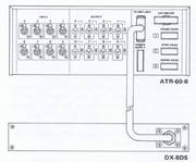
- die Recorder-Rückseite

The TASCAM DX-8DS is a specially designed 8-channel noise reduction unit that provides dbx* Type 1 Tape Noise Reduction for the ATR-60-8. The front panel of the unit has two sets of switch legends, one for channels 1-8, and the other for channels 9-16; the latter does not apply to the ATR-60-8, but is used for when two DX-8DS units are used with a 16-track TASCAM recorders such as the MS-16.
The DX-8DS is automatically controlled so that non-encoded signals are always available at the outputs of the recorder. Once connected to the ATR-60-8, the DX-8DS and the recorder function as a unit. There is no need for special record or reproduce level calibration procedures.
Der dbx processor compander Type 1
The dbx processor is a compander, providing 2:1 compression of the input signal during recording, and complementary 1:2 expansion of the output signal upon playback.
The actual operation of the dbx circuitry is somewhat more complex, and includes up to 12dB of frequency-dependent signal pre-emphasis and de-emphasis to overcome tape modulation noise. The result of dbx processing is that recording headroom is improved by approximately 10dB, and overall record/play signal-to-noise performance is improved by up to 30dB as compared to a non-dbx encoded tape.
Encoded tapes (tapes recorded with dbx processing) will sound excessively noisy, deficient in bass, and very compressed if played back "without" the complementary dbx decoding.
Normal (non-dbx encoded) tapes will sound bass heavy, deficient in high frequencies, and will surge in volume if played back with dbx decording. There is no compatibility between Dolby* noise reduction and dbx noise reduction systems, nor is there any reason to utilize Dolby NR if dbx is employed.
dbx Type II
There is another dbx tape noise reduction standard, known as dbx Type II. That system was developed primarily for consumer (rather than professional) applications that involve cassette tapes and phonograph records (which are more often subject to irregular high and low frequency response).
For this reason, dbx II processing is less sensitive in its level sensing circuitry below 30 Hz and above 10 kHz. As a result, tapes made with dbx I processing may not be properly decoded with a dbx II decoder, and vice-versa.
Die Anzeigen bei dbx Aufnahmen
Because dbx noise reduction compresses the signal applied to the tape, the ATR-60-8 VU meters will not deflect as widely as with an unencoded signal. The record levels may also be lower. This is normal with the dbx processing, and you should not try to increase the levels to obtain the higher peak levels that would be obtained without dbx processing, as this would defeat the headroom advantage of the dbx processing. Instead, calibrate the mixer or mixing console with the dbx unit switched to BYPASS position.
* dbx is the registered trademark of dbx. Inc., Newton, MA. The TASCAM DX-8DS is built under license from dbx, Inc. Dolby is the registered trademark of Dolby Laboratories Licensing Corporation, San Francisco, CA.
NOTE: If you are recording or playing SMPTE/EBU time code on track 8, be sure to place that channel of the DX-8DS in BYPASS mode. Time code signals do not require noise reduction processing, and due to the nature of the digital signal, the unnecessary extra processing can actually cause misreading of the code.
3.4.2 Hookup of the DX-8DS
Turn off power on the ATR-60-8. Then connect a multi-pin cable from the DX-8DS to the connector on the ATR-60-8 amplifier module rear panel marked "TO DBX UNIT." The DX-8DS audio inputs and outputs are carried to the ATR-60-8 by the same multi-conductor cable that handles power and logic. The "CH 1-8" LED will be illuminated on the DX-8DS when power is turned on, indicating the unit is serving the 8 channels of the ATR-60-8. Refer to Figure 3-7.
CAUTION: When the DX-8DS is not used, the jumper connector shipped with the ATR-60-8 must be installed in the "TO DBX UNIT" connector on the amplifier module. Otherwise, no audio signal will get through the tape machine!
3.4.3 DX-8DS Specifications
| Number of Channels = 8 channels | (8 Encode / 8 Decode, separate controls), Type I |
| Encoder Section Input (at 1 kHz): Input Impedance | 50kOhm |
| Nominal Input Level | -10dBV (0.3V) |
| Maximum Input Level | +16dBV (6.3V) |
| Output (at 1 kHz): | |
| Output | 220kOhm |
| Impedance Nominal Load | 50kOhm |
| Impedance Minimum Load | 4kOhm |
| Impedance Nominal | -10dBV (0.3V) |
| Output Level Maximum | +16dBV (6.3V) |
| Output Level Decoder Section | |
| Input (at 1 kHz): | |
| Input Impedance | 50kOhm |
| Nominal Input Level | -10dBV (0.3 V) |
| Maximum Input Level | +16dBV (6.3 V) |
| Output (at 1 kHz): | |
| Output Impedance | 220kOhm |
| Nominal Load Impedance | 50kOhm |
| Minimum Load Impedance | 5kOhm |
| Nominal Output Level | -10dBV (0.3V) |
| Maximum Output Level | +16dBV (6.3V) |
| Frequency | 40Hz- 15kHz ±1dB |
| Response (Encode/Decode) | 30Hz-20kHz ±2dB |
| Distortion (Encode/Decode) | 0.2% at 1 kHz |
| Noise Reduction | More than 30 dB |
| Dynamic Range | 100dB |
| Power Requirements | Powered from the ATR-60-8 |
| Dimensions | 482 x 88 x 300 mm |
| (WxHxD) | (19" x 3-7/16" x 11-13/16") |
| Weight | Approx. 5 kg (11 lbs.), including cable |