
Wir bekamen es leider erst sehr spät zu lesen, das ganz frühe Wissen der USA vom 25. November 1945 - Das Wissen über
"GERMAN SOUND RECORDING"

In 2019 haben wir diesen amerikanischen 60 Seiten-Report vom 25. November 1945 per Mail fast anonym "zugespielt" bekommen.
Die Amerikaner (die Beamten im Wirtschafts -ministerium) wußten also auch in der Ost- Küsten- Administration (in Washington DC) ziemlich früh und schnell von den deutschen AEG Magnetophon's, eigentlich schon früher als die allermeisten Ingenieure aus der Tontechnik in Californien in den Filmfabriken an der Westküste der USA.
Denn dort hatte ja "nur" (und das stimmt damit überhaupt nicht mehr !!!) der Signal Corps Offizier Jack Mullin zwei solcher älteren AEG K4 mit alter Gleichstrom Vormagnetisierung "herübergeholt" und diese nach den bei Radio Frankfurt "abfotografierten" Schaltplänen !!! dann bei sich zuhause in Californien "HF-modifiziert" und in Betrieb genommen (und angeblich diese wichtige Modifikation natürlich niemandem verraten). Es hatte ja in Californien angeblich sowieso "keiner" Ahnung von dieser völlig unglaublichen Qualität.
Das stimmte so aber auch wieder nicht, denn Jack Mullin hatte dem Ampex Chef Alexander Poniatoff eine Absage erteilt, er könne nicht für Ampex arbeiten, er habe bereits einen Beratervertrag mit Colonell Richard Ranger, der auch ein Magnetophon K4 aus Deutschland selbst "mitgebracht" hatte (oder "erhalten" habe ?).
Die Wege der deutschen Kriegsbeute, der neuartigen AEG-Magnetophone rüber in die USA (es waren an die 100 AEG K4 in ganz Deutschland im Einsatz) waren damals alle sehr "geheimnisvoll und verschlungen".
Das mit dem Magnetophon wurde schon 1946 publiziert .....
- Ausgabe Dezember 1946

In einer (auch sehr seltenen) US-Zeitschrift des New Yorker Schallplatten-Schneid-Folien-Herstellers "audio-devices" (Ostküste) wird dort - aber erst Ende 1946 - von dieser neuartigen Magnetophon-Technik aus Nazi-Deutschland und vor allem - es war ja für das eigene boomende Schneidfolien-Geschäft von "audio device" absolut geschäftsschädigend - von dieser neuen überaus "gefährlichen" Konkurrenz berichtet.
Wenn man aber bis etwa 2018 in Suchmaschinen nach der Historie und den Wissensquellen der amerikanischen Magnetbandgeräte sucht, kommt man fast überall unweigerlich auf die über Jahre sicherlich ganz geschickt lancierten Promotion-Artikel von Jack Mullin und auf die "glorreiche Historie" der Bandgeräte- Firma AMPEX in Californien. Auch die Firma 3M fuhr ihre patriotische Werbung auf dieser Schiene. Das war schon gut gemacht, nur, es stimmte aber nicht.
Diesen hier auf dieser Seite vollständig enthaltenen "SRM-1" Report vom Nov. 1945 hat vermutlich ein beteiligter Offizier des US-Signal-Corps geschrieben, der zumindest teilweise der Deutschen Sprache mächtig war. Dafür sind die beschriebenen Eigenschaften und Besonderheiten viel zu datailliert. Und außer den Vorführungen des "OTS", des "Office of Technical Services" in Washington DC gab es parallel dazu die sogenannten "FIAT Reports" (http://www.cdvandt.org/fiat-705.htm).
.
"Intelligence Report" about "GERMAN SOUND RECORDING"

Technical Liaision Division - HEADQUARTERS THEATER SERVICE FORCES - EUROPEAN THEATER - OFFICE OF THE THEATER CHIEF SIGNAL OFFICER
(Rear) APO 887 - 25 November 1945
(Anmerkung : APO und FPO sind amerikanische militärische Post-Office Adressen (simple Postfächer) für im Einsatz befindliche Militärangehörige in Europa oder im Pazific )
.

.
Intelligence Report (SRM-1) MAGNETIC "SOUND RECORDERS MAGNETOPHONE" and "TONSCHREIBER"

ABSTRACT : This report describes the "Magnetophone" and "Tonschreiber" sound recorders.
In principle the same, several models of each provide recording facilities for any purpose from code recording in front lines to extremely high quality installations in Broadcasting stations. Details of the mechanisms, electrical circuits and the magnetic tape employed for the records are set forth (JTM) - 25 November 1945
.
Vorwort und Einleitung zu diesem Dokument aus Nov. 1945
Hier hat ein amerikanischer Autor (vermutlich ein Offizier) sein Wissen von November 1945 aufgeschrieben und amerikanischen Regierungsstellen sowie der amerikanischen Wirtschaft und anderen Interessenten zur Verfügung gestellt. Von Patentklau und all dem anderen - in unseren Nachkriegszeitschriften lancierten - Unsinn kann damit in keiner Weise die Rede sein, sondern eher von "Reparationen" - aber immer nach den jeweils gültigen Patentgesetzen in den jeweiligen Ländern.
Mehr fachlich fundierte Informationen zu den in unseren deutschsprachigen Medien über viele Jahrzehnte immer wieder wiederholten falschen "Legenden" und falschen oder sogar ziemlich dummen "Berichten" über die deutschen angeblich geklauten oder konfiszierten Patente im In- und Ausland steht hier ganz ausführlich auf der Patent-Seite im Fernsehmuseum.
.
MAGNETIC SOUND RECORDES MAGNETOPHON and TONSCHREIBER - I N D E X -

I - Introduction, .......................................... Page I
II - Types of German Tape Recorder, ........ Page 3
III - Evaluation of the Recording System, . Page 4
IV - Magnetophon Recording Process, ....... Page 5
V - Details of Magnetophons, ...................... Page 11
VI - Descriptions of Tonschreiber Series, .. Page 23
Appendix A :
The Magnetophon Method ( Translation of an German article on recording system and tape production) .. Page 28
.

- LIST OF FIGURES -
Fig, 1 Linear magnetized recording
Fig, 2 Cross-magnetized recording
Fig, 3 Erasing and recording heads
Fig, 4 Comparison of DC and Supersonic Systems
Fig, 5 Mechanism of HT2 and K3 Magnetophon
Fig, 6 Mechanism of K4 Magnetophon
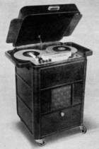
Fig, 7 Picture of K4 Magnetophon
Fig, 8 Circuit of K4 Playback Preamplifier
Fig. 9 View of Zwillingsgeraete Magnetophon
Fig. 10 View of Zwillingsgeraete Magnetophon
Fig. 11 View of Zwillingsgeraete Magnetophon
Fig. 12 Circuit of Playback Preamplifier V5
Fig. 13 Circuit of Playback Preamplifier V6
Fig. 14 Response-curves of Preamplifier V6
Fig. 15 Circuit of D.C. Recording Equalizer V7
Fig. 16 Circuit of Supersonic Recording Amplifier V7b
Fig. 17 Response curves of Recording Amplifier V7b
Fig. 18 Circuit of Playback Preamplifier V7a
Fig. 19 Response curves of Preamplifier V7a
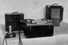
Fig. 20 Picture of Tonschreiber b
Fig. 21 Picture of Tonschreiber c
Fig. 22 Samples of Type "C" and Type "L" Tape,
.
Vorab ein paar notwendige Übersetzungshilfen :
(1) Das Wort "mechanism" wurde später (bei den Amerikanern und Japanern) als "transport" oder "Antrieb" benannt. Der sogenannte "tape transport" war das Bandlaufwerk ohne die Elektronik, wie es bei den deutschen Profigeräten auch üblich war. Bei uns in Deutschland war das später immer ganz einfach das "Laufwerk" oder das Geräte-"Chassis".
(2) Die "ball-mill" war bei uns die sogenannte "Kugel-Mühle", in der das magnetische Gemisch bei erhöhter Temperatur gemahlen und zu Staub verkleinert wurde.
(3) Und unter "cement" verstanden die Amerikaner den ganz gewöhnlichen "Klebstoff" oder "Kleber", beim Zweischicht-Tonband auch das "Bindemittel" genannt.
(4) Die öfter vorkommende "flywheel" ist die Schwungscheibe oder das Schwungrad an der Capstan- oder Antriebes-Welle eines Bandgerätes.
.
I - INTRODUCTION
- 1945 mit Schreibmaschine geschrieben

In magnetic sound recording, a wire or tape is pulled past a recording head and receives a magnetization corresponding to the audio being fed to the recording head. The magnetized tape can subsequently be pulled past a playback head, in which it induces a replica of the signal which magnetized it.
The first commercial magnetic sound recorder was the "Telegraphone" introduced by Poulsen in 1900. This device employed a steel wire about 0.010 inches in diameter, but was seriously limited by a poor signal-to-noise ratio and a high wire speed.
The "Blattnerphone", introduced several years ago, uses a steel tape about O.OO3 inches thick and 3/8 inches wide. This tape, running at 100 meters per minute, can reproduce up to about 8.000 cycles per second, but the volume range and signal-to-noise ratio are somewhat inadequate, so that its principle employment is in radio broadcasting in England and on the Continent, where it is used only for voice and heavily monitored dance music.
These systems employ a longititudinal magnetization process, with pole pieces arranged is shown in Figure I.
.
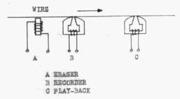
- Figure 1. Stahldraht (wire)

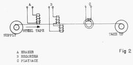
- Figure 2. Magnetband (tape)

Bell Telephone Laboratories have developed a cross-magnetization system, with poles arranged as in Figure 2. This enables the recording to be made across the tape, so that tape speed can be reduced to 12 inches per second for recording up to 6.000 cycles per second. A volume range of 35db was made possible by the improved signal-to-noise ratio of this system.
The current Western Electric and Bell System magnetic recorders use this principle. During the war, the Armour Research Foundation has developed an extremely light-weight wire recorder which, however, has no provision for constant wire speed, and is still not a high-fidelity recording equipment.
The most outstanding recent advance in the field of magnetic recording has probably been made by the German Allgemeine Electricitäts Gesellschaft (AEG) in its development of the Magnetophon and Tonschreiber series, which record on plastic topes about 0.04in thick and 6mm wide, either coated or impregnated with microscopic particles of magnetic material.
The Magnetophon series was first introduced about 1937 and subsequent models have incorporated improvements in performance till the present equipment is the standard high-quality recording system used throughout Germany in the radio broadcasting service. For military use the Tonschreiber series provide models with specialized facilities for intercept, portable use and other applications.
The excellent performance of the latest Magnetophon recorders is due to the use of the plastic tape recording material, to the use of an improved system of recording and erasing with supersonics, and to on excellent mechanical construction, insuring absolute constancy of tape speed.
These magnetic tape recorders represent the only significant development in this recording field by the Germans. It is known that Lorenz produced small numbers of conventional wire recorders for dictaphone and speech recording, but their performance was not outstanding and they had no significance in military or high quality commercial recording.
II - TYPES OF GERMAN TAPE RECORDERS :
.
Magnetophon Series
- Die T2 Truhe

- ein erster Koffer

The commercial Magnetophon was first introduced about 1937 (stimmt nicht ganz, es war Septmber 1935 zur Funkausstellung) and subsequent models have introduced on basic mechanical change and one significant electrical change.
The first model to achieve much use was the H T-2, a heavy, immobile machine in a plywood cabinet, which also contained the speaker and amplifier.
A portable version known as the K3 was later introduced, but this was soon followed by a mechanically improved portable machine, the K4, which remains the standard portable equipment.
Several thousand of these have been produced, and they have found widespread use in radio stations, Reichspost monitoring service, and other recording amplications.
For particular applications, small numbers of special models have been built. One example is the RF7 R2h Zwillingsgerate built for the Reichspost.
This was basically the mechanical portion of two K4 models end a special electrical panel, arranged to provide continuous, semiautomatic recording for monitoring purposes.
Das AEG K7

The latest model in service is the Magnetophon K7, which is a semi-fixed installation used by the broadcasting service as their standard sound recording system. The mechanical portion is usually mounted in a table, with the electrical circuits in a standard rack nearby. This is the model which incorporates an improved erasing and recording process to provide what is probably the finest commercial recording system in existence.
- Anmerkung : Das stimmt so nicht, denn von den K7 gab es nur ganz wenige. Das H.F.-modifizierte AEG K4 war ab 1941/42 das Standardgerät der Reichspost und des Reichsrundfunks.
.
Tonschreiber Series

Three basic military recording sets have been produced by AEG, under the name "Tonschreiber". The most elaborate is the "Tonschreiber b", which provides line voltage operation (damals waren das 220V), variable tape speed and special intercept facilities.
The "Tonschreiber c" is a small, battery operated set for front-line use. It is constructed in two cases : a recorder which is spring-driven, and a playback case which is battery-operated. The "Tonschreiber d" is a larger, battery operated portable set, intended for field intercept, but includes no special intercept features and has a fixed tape speed.
Further details on the various models of the Magnetophon and Tonschreiber will be given following the discussion of the principles and practises followed by AEG in this recording system,
III - EVALUATION OF THE RECORDING SYSTEM :
A Magnetophon recording is ready for use the instant it is made, and may be monitored during the recording. The tape can be erased and recorded an unlimited number of times and can be played back thousands of times without detectable deterioration in quality.
Unlike mechanical and photographic processes, recording adjustments are not critical and over-modulation merely produces a gradual increase in distortion as the magnetization curve becomes non-linear. The tape can readily be edited, cut, spliced and corrections made by re-recording any unsatisfactory portions.
The tapes are easily handled and shipped without fear of breakage. A 1.000-meter roll of tape, some 10 inches in diameter and weighing about the same as 2 twelve-inch shellac records, gives over 20 minutes playing time on the high-fidelity machines, but this may be doubled or quadrupled when slower tape speed is used, with a corresponding decrease in the available frequency range.
It may be noted, that the early tape materials tended to deteriorate plysically after long storage, becoming brittle. They seem to maintain their magnetic characteristics permanently, however, and it appears that the latest impregnated plastic tapes do not suffer this aging.
.
Also, the machines are designed with typical German thoroughness, and appear heavy and complicated by American engineering practices. In some models the tape threading appears unnecessarily difficult.
- Anmerkung : Als Muster-Beispiel diente mir das amerikanische Viking 88 Bandgerät von etwa 1964. Dort haben die Amerikaner genial gezeigt, mit wie wenig Technik man dennoch ein erstaunlich professionelles Bandgerät konstruieren konnte.
The latest high-fidelity Magnetophon Type K7 has a useful dynamic volume range of 65 to 80db, a frequency range of 25 to 10.600 cycles per second, and the signal-to-noise ratio is for all practical purposes that of the associated amplifiers.
- Anmerkung : Diese db Angaben sind sicher ohne Bewertung gemessen oder publiziert. Nach unseren deutschen Nachkriegs-Normen waren das nur maximal 56db signal to noise. Mehr konnte das K4/HF auch nicht. Da das AEG K8 von 1946 bis 1948 nahezu baugleich war, sind diese 56db Angaben glaubwürdig.
The preceding models of the Magnetophon and "Tonschreiber" series, using D.C. erasing, have a signal-to-noise ratio of about 38db and are limited by the associated amplifier equipment to a maximum frequency range of about 50 to 5500 cycles per second, when a tape speed of 77 centimeters per second is employed. Certain models are restricted to an even smaller frequency range by slower tape speed, or by band-pass recording amplifiers.
In appraisal, it may be stated that the latest high-fidelity Magnetophon offers performance not surpassed in any commercial equipment, and has, in addition, features not offered by any other system.
However, the earlier DC erasing models and the "Tonschreiber" Series, while presenting certain special features and advantages, are inferior in quality to other available systems.
IV - MAGNETOPHON RECORDING PROCESS :
The Magnetophon magnetic recording process is similar to the longititudinal system shown in Figure I, and consists of three stages : preparation of the tape (erasing), recording, and playback,
Preparing the tape (erasing)
The tape is prepared for recording by erasing any signal on it, and placing it in magnetically neutral condition. It may be erased by magnetizing it to saturation with a strong field from a D.C. energized magnet, or by "degaussing" it with a strong high-frequency magnetic field much as a jeweler demagnetizes a watch. This latter process is a recent development which is incorporated only in the latest model Magnetophon. (Anmerkung : ab 1941 Model K4)
H.F. - high frequency erasing
If high frequency erasing is used, the tape is left in a magnetically neutral condition. If D.C. erasing is used, the tape leaves the erasing coil in a saturated condition, and is brought approximately to neutral during the recording by passing a small direct current through the recording coil in addition to the audio signals.
.
D.C. erasing
The D.C. erasing head shown in Figure 3 is used in all Tonschreibers and in all Magnetophone, except the latest high-frequency erasure model, it is fed with well-filtered D.C. from a high-voltage supply, or from batteries, and a typical arrangement may be seen later in this report in the circuit diagram of a recording equalizer.
.
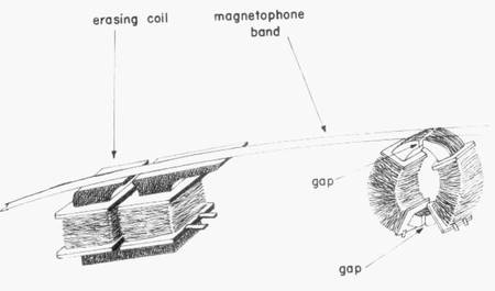
- Firgur 3 - die Tonköpfe

.
The high frequency erasing head appears to be a recording head as seen in Figure 3, modified by a brass shim in the gap, to give a gap-width of some 1,5 millimeters, and by use of a low-impedence winding to facilitate matching to the high-frequency source.
The coil is fed in series resonance from a single 6 watt tetrode self-excited oscillator at a frequency of about 40kCs (Kilohertz) and receives enough energy to run slightly warm. In a manner anelagous to the optical slit limitation in motion picture sound recording, the gap in the erasing coil is too great for the super-sonics to record, and the tape is left in a neutral state as it passes out of the field of the erasing head. The details of this eraser will be found later in the report, in the circuit of the V7b recording amplifier.
.
D.C. erasing system
In the D.C. erasing systems provision is made to switch an inductance capacity network across the erasing and recording coils when the recording circuit is switched off. This lets the coils release their stored energy in an oscillatory discharge, effectively de-mcgnetizing them to prevent any effect on tape which may be run past them. In the high-frequency system this precaution is not nessecarry.
The supersonic erasing process leaves the tape in a very quiet condition, but the D.C. erasing and neutralization leaves a rather high noise level.
As materials undergo magnetic changes in steps or increments, rather than smoothly and continously, the lower noise level produced by the supersonic erasure probably occurs because the increments are smaller and more frequent in this case than in the D.C. method.
.
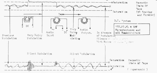
- Figure 4 Teil 1

.
Figure 4 gives a diagrammatic comparison of the erasing, recording, and playback sequence as accomplished by the D.C. process and as done by the high-frequency system.
.
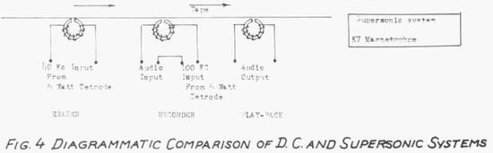
- Figure 4 Teil 2

.
Recording
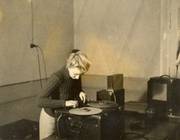
- Dr. Gertraud Simon mit Magnetophon 1941

In all models of the Magnetophon and Tonschreiber, recording is accomplished with a head such as is shown in Figure 3, with a recording slit of 0,02 mm width between the polepieces. The only apparent variation between the recording heads used in different machines is in the impedence of the coil bindings.
Audio signals, fed to the coil, produce a magnetic field across the recording slit which varies in accordance with the audio current in the coil. As the tape passes across the recording head, it assumes a magnetization corresponding to the field across the slit at that instant.
Thus, the recorded tape may be thought of as resembling a variable density movie sound track, with the density variations replaced by magnetic variations.
If the tape has been prepared for recording by the D.C. erasing process, it arrives at the recording coil in a saturated condition, and to bring it to magnetic neutral, the recording coil is fed a direct current of half the value necessary to saturate the tape in the opposite direction.
Thus it is returned approximately to neutral during recording. This "premagnetization" current during recording also serves to get the tape "in motion" magnetically, reducing the inertia which the audio signal must overcome.
The required current varies with each recording head and the proper value, determined by experiment, is noted on the head.
Distortion und HF Vormagnetisierung
When the tape has been erased by the supersonic process, it arrives at the recording head in a magnetically neutral state. However, if an attempt is made to record merely by feeding audio to the head, considerable distortion results, due to the "inertia" of the tape, and to the magnetization occuring in steps, or increments.
This distortion can be eliminated if, in addition to the audio signal, the recording head is fed a supersonic signal of sufficient amplitude to "agitate" the tape, overcoming its magnetic inertia. This technique, used in the K7 Magnetophon, gives an exceptionally good signal to noise ratio and makes possible the splendid dynamic range of this set.
- Anmerkung : Das war auch bei den modifizierten AEG K4 Geräten bereits so, also nicht erst bei den K7 Geräten.
The details of the supersonic recording circuit may be seen later in the schematic of the V7b recording amplifier. A 6 watt self-excited tetrode oscillator is used, operating at a frequency of 80 to 100 KC (kilocycles).
This frequency, which is not critical, is made variable to tune with a rejection filter intended to keep the superscnics out of the audio channels. The amplitude of supersonics fed to the recording head is controllable, and is stated to have an optimum value for the best signal-to-noise ratio.
The amount of audio power needed for recording is exceedingly small. In some of the Tonschroiber series, sufficient power for recording is obtained directly from the headphone-output of a radio receiver, or even from the telephone lines, but in the Magnetophon series, the signal is taken at low impedance from an amptlifier, through equalizing networks.
.
Recording Equalization
As the field strength across the recording slit is proportional to the current in the coil, and the coil presents an inductive load, it is fed from a beam-tetrode in the Magnetophon to approach constant-current operation. This gives an essentially flat recording characteristic up to the frequency at which an appreciable change in the signal cycle occurs during the time the tape moves a distance equal to the slit width.
Above this point, the high frequencies are accented in recording to compensate for the loss that occurs due to the width of the slit, corresponding to optical slit loss in motion picture recording.
In addition, since tape noise and amplifier noise lie predominantly in the higher frequency region, it has been found that the overall signal-to-noise ratio can be greatly improved by pre-emphesizing the high frequencies in recording, with a corresponding attenuation in playback.
This is practiced in the Magnetophon recording amplifiers and equalizer curves and circuit details may be obtained from the descriptions of specific sets. It is typical practice to provide an overall recording curve in which the current at 9 KC is from 4 to 12 decibels above the 1 KG reference value.
Playback Heads
All Tonschreibers and Magnetophons use playback heads which appear identical to the recording head shown in Figure 3 and seem to differ only in the impedance of their windings. When a magnetized tape is pulled past this head the coil delivers a voltage which is a replica of the signal that magnetized the tape.
A tape recorded with a constant current-versus-frequency characteristic, delivers a playback output voltage wich rises with frequency, as the tape and playback head may be regarded as a generating system in which the output voltage is a function of the rapidity with wich the flux changes occur.
Playback Equalization
To compensate for the rising playback characteristic, and the high accentuation introduced in recording, a simple resistance-capacity equalization circuit is incorporated in the playback amplifier.
A typical circuit is shown in Figure 18, with the characteristic response curve produced. Certain models of the Magnetophon also include resonant equalization circuits, to boost the extreme bass range, or to secure a sharp cutoff of the high end. Details of the various arrangements may he found in the schematics of the playback amplifiers,
mechanical system
The mechanical system in the MTagnetophons and Tonschreibers serves to pull the tape past the head at a constant speed in recording and playback, and to rewind in the reverse direction, usually at a much higher speed. All models of the Magnetophon use almost identical mechanical systems, but three different arrangements are found in the Tonschreibers.
A view of the basic Magnetophon mechanism may be seen in Figure 10 in the description of the Zwillingsgeraete. The tape, in self-supporting rolls on metal hubs, is placed on horizontal flat aluminum discs for playing.
The feed hub mounts directly on the shaft of a commutator-type series-wound motor. The take-up hub is mounted directly on a similar motor. The tape is pulled past the head at constant speed by a synchronous motor, and the two previously noted motors serve merely to pay out and take up the tape under tension.
The feed motor is energized at reduced power during recording or playback, when it serves as a brake. During rewind, the synchronous motor is disengaged from the tape, the feed motor energized at full power, and the take-up motor de-energized.
The Magnetophon mechanisms are fitted with selenoid brakes which drop in instantly on switching off, to prevent slack in the tape.
A governor on each series-wound motor prevents them running away if switched on without load. Series-wound feed and take-up motors are used to secure a torque-vs-speed curve which would keep the tape under fairly constant tension throughout a reel. The synchronous constant-speed motor is fitted with a blower to cool itself and the other two motors.
Weiter mit der Mechanik
The same basic mechanism has served as the foundation of all models of the Mlagnetophon from the HT-2 to the latest model, indicating that its performance is satisfactory.
It is understood that some broadcast stations have experienced overheating troubles when the set was built into a console without full ventilation, and it is noted that radio frequency filter system has been built in to suppress interference from the motor brushes. Descriptive literature notes that the slow speed of the feed and take-up motors is not conducive to long brush life51 but the users do not mention trouble from this cause.
The Mfagnetophon mechanism gives absolutely wowless, flutter-free performance, and even the most critical appraisal will find nothing to criticize in the results achieved by it.
In all Tonschreibers, the tape is used on reels similar to motion picture reels, to allow operation in any position and make tape handling easier in field operation. Mechanical brakes are used to provide film tension and prevent coasting.
Eigenschaften der "Tonschreiber"
In the variable-speed "Tonschreiber b", the tape is pulled past the heed by an AC motor on which the supply voltage is adjusted to bring it aproximately to the correct speed, and it is locked into step with a small synchronous motor driven by a variable-frequency audio oscillator,
In the "Tonschreiber c" the recording is done with a spring-driven flyball-governed motor which pulls the tape and also drives the take-up reel through a belt. The recording unit does not rewind. The playback unit has a battery-driven, reversible flyball-governed motor which pulls the tape and drives the reels through belts.
The "Tonschreiber d", which has the record and playback facilities in one case, has a battery-driven flyball-governed motor to supply power.
Magnetophon HT2
This recorder is a very early model of the Magnetophon. It was housed in a plywood box abaut 90cm long, 60cm wide and 120 centimeters high. The cabinet contained a loudspeaker in the front, behind which were control relays and the amplifier equipment. The mechanism was in the top of the cabinet beneath a plywood lid.
While the Tonschreiber series may be operated with the face of the mechanism horizontal or vertical, this set, like all Magnetophons, was designed for horizontal operation only.
The diagram, Figure 5, shows the layout of the main components. A pair of spindles 1,2 provide mounts for the supply spool and take up. A film (sicher ist hier "tape" gemeint) to be played passes from the supply reel around roller 3 to the recording and playback coils 4 and 5 respectively.
The signals generated in coil 5 are passed to the amplifier for reproduction and the tape is wound about the hub 6. No reels are employed. The tape is wound sufficiently tight to be removed, with the hub, as a self supporting disc when taken from the machine.
While the take up hub 6 is driven by a directly coupled series commutator type motor the tape is actually driven at constant speed past the sound head by a synchronous motor between whose shaft 16 and a rubber idler 17 the tape must pass. A third motor, identical with the first, provides a direct coupling to the supply spindle. This is actually the rewind motor. It is the same type motor as that on the take up but it runs in the reverse direction when energized.
Even when the tape is running forward the rewind motor is energized by low voltage. This assures a uniform tension in the tape as it is being run through the machine.
V - DETAILS OF MAGNETOPHONES :
.
Probleme mit den Asynchronmotoren
Each of the three motors contains within its frame a brake drum and felt lined band which is applied instantly by release of a solenoid individually mounted on each motor when the power is removed. This maintains the tape in uniform tension, preventing formation of loops and consequent snapping of the film band. The rewind and take-up motors also contain built-in coaxial fly ball governor to prevent their running away when not loaded. This could occur with possible destruction of the motor since they are of the "series type".
The "Tonmotor" or synchronous film propulsion motor contains the aforementioned brake plus a fan which circulates air to the other two motors as well as itself, by means of an air duct system. ( See the illustrations of the internal construction of the RPF R 2h Zwillingsgerate, since this arrangement is still in use at the present time).
Die 4 Drucktasten (Anmerkung : ab AEG K2 aufwärts)
Four control buttons are provided. Pressure of the "Wiedergabe" (play-back) button 9 propels the film forwarded by energizing all three brake solenoids, and applying full 220 volts to the "Tonmotor" (film drive motor)and the take up moter.
The rewind motor is energized at low voltage under these conditions. Depressing the "Halt" (stop) button 10 mechanically unlocks the previous button and mechanically unlocks the previous button and the mechanism instantly comes to a stand-still.
Depressing the "Ruecklauf" button 7 deenergizes the take up motor completely and applies full voltage to the rewind motor while again energizing the three brake solenoids.
.
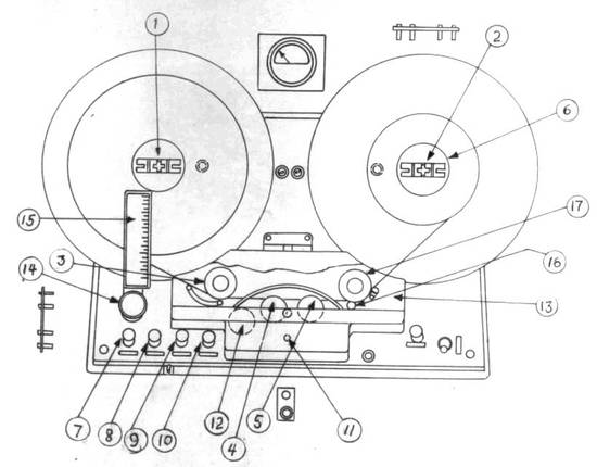
- Ein für diesen Report nachgezeichnetes AEG K2 / K3 (nicht K4 !) Forntansicht mit Referenz-Nummern

.


A fourth solenoid which brings the rubber idler into play with the tonmotor shaft is left denergized in the rewind position. This enables the tape to be speedily rewound to the left spindle.
To record it is necessary to press the "Aufnahme" (record) 8 button. This drives (the tape forward in a manner similar to that previously described, but a fifth solenoid is energized which rotates the recording playback head through a small angle about the pivot 11.
This brings the erasing coil 12 and recording coil 4 into contact with the tape. At the same time relays are operated which reconnect the amplifier to the recorder and supply the erasing coil with direct current for saturating off the previous recording.
A required LC component is provided for the recording coil. The recording, reproducing and erasing coils are covered by a hinged lid 13 which must be opened to thread the apparatus. The playing time scale 15 is rotated to clear the roll of tape by turning knob 14.
.
Die Bandteller

See Magnetophon K4 and R7 for details of the method of actually recording the signal in this machine. This is the same method employed in all Magnetophons and Tonschreibers, except the R7.
The rolls of tape employed in the HT2 machine are 1.000 meters in length, and are run at 72cm per second. This provides a running time of 22 minutes. The limitations of this machine were narrow frequency band and high signal to noise ratio. The machine was useful to 4.000 cycles, but the S/N ratio was only 30-35db.
"The characteristic noise of such a machine is a rushing sound similar to the noise produced by letting water run in a bathtub when the listener is outside the bathroom with the doer closed between". Apt or inapt, the description serves to illustrate the ennoying of such limited volume range.
Magnetophon K3 (Koffer Modell 3)
- AEG Magnetophon K2 Koffer

The first important portable machine was the K3. This was made up in three boxes, the largest containing the mechanism, which was identical with that of the HT2, shown in Figure 5. A second box contained the amplifier and a third housed the loudspeaker. The completed machine was much the same as the K4 in physical appearance, performance was about the same as the HT2.
With their limited signal-to-noise range, music could not be satisfactorily recorded except for test purposes, the disturbing reminder of water running into the bathtub remaining a desillusioning effect.
Magnetophon K4

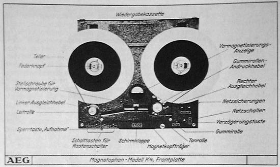
A change in mechanical design was inaugurated prior to the introduction of the K4. Figure 6 shows an outline of the face of this machine. The principle differences are the inclusion of the playback preamplifier I and a modified sound head 2.
A flywheel loaded roller 3 is used in place of the free roller formerly employed and improves the velocity constancy of the tape. The playing time scale is eliminated and an improved fastener is employed to hold the tape hubs onto the spindles.
Der im K4 integrierte Vorverstärker
- Das AEG K4 mit reinem Mikrofon- und Verstärkerkoffer

The preamplifier is built into the rear of the carrying case and adds some depth to the box since the mechanism framework is of the same dimensions as that of the K3.
The preamplifier employs two metal type tubes as pentodes, with DC on the filaments derived from a bridge selenium rectifier. Removal of a small cover between the tape plattens reveals two controls. One of these is a tone control and the other is an output level control.
The tone control acts to change the level of the high frequencies only. The inclusion of the preamplifier within the framework of the mechanism was apparently brought about in order to provide a highlevel output for decreased noise.
It enables the mechanism to be used to provide a level of about 1/2 volt at 10,000 Ohms or 10mv at 200 ohms without using any external equipment. Machines tested by this office have not been particularly quiet, however. Tube hiss and 50 cycles hum have been much higher than the level measured in a high gain broad band American amplifier employing selected 6SJ7 tubes as pentodes in the first two stages.
Der Kopfträger und die Köpfe des K4
- aus einer AEG Publikation

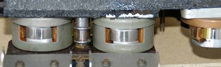
The sound head (gemeint ist der Kopfträger) in the K4 is readily replaced by loosening the two screws 4-4. The head lifts off as a unit containing the three coils, the eraser coil 5, recording coil 6, and playback coil 7.
The erasing coil and one of the recorder-reproducer coils, which are identical in all respects except impedance were previously showm in Figure 3. The core of the erasing coil is of soft iron and has regligable retentivity. The construction is straightforward; the attempt being to produce a maximum field strength at the gap between the poles.
Die Besonderheiten der K4 Köpfe
- Achtung : Das Band läuft von rechts nach links K8 Kopfträger)

The recording and playback coils are more interesting. They are wound on special bakelite bobbins which are placed on laminated crescent shaped cores. The material of which the core is composed must have very low retentivity and the laminations are extremely thin.
A bronze spacer (Abstandhalter) forms a gap et the top of 0.02mm when two such forms are assembled into the completed unit, but a much larger air gap is provided at the botton of the assembly.
This seems to vary somewhat with different coils, being about 1/4 millimeter average length. The entire coil assembly is less than an inch in diameter and its two coil and core elements are clamped rigidly into a unit by small die cast covers at front and rear.
As previously stated the sound head contains two such coil assemblies and the erasing coil. All are isolated, by magnetic shields and a small cover which leaves plenty of clearance for the tape to pass through the head but which isolates the recording coil from the reproducer.
Neu beim K4 - Hinterbandkontrolle
The complete head carries six pin connectors which plug into the frame of the machine when the head is put in place. The tape runs at all times in contact with all these coils. There is no rotation of the head to bring the erasing and recording coils into play when a recording is to be made, as was done in the HT2.
The advantages of easy interchangeability and mechanical simplicity make this a worthy inprovement over the earlier machines. An added advantage of the newer head is that it permits instantaneous playback monitoring, if a separate amplifier is available since a recording can be erased and another put on the tape and immediately played, all in one operation. The built-in pre-amplifier has a headphone output for use in monitoring during recording.
Der Frequenzgang des AEG K4
The response characteristics of this machine are highly improved over the former units. The curves show a rising overall response up to 5000 cycles.
Useful response is still to be obtained at 6.000 cycles but beyond this frequency the response is not good. Low frequency response is completely satisfactory. The machine is not suitable for high quality music recording because of one serious factor. The signal to noise ratio is not adequate to give a useful volume range. The limitations of Ht2 and K3 apply with but little improvement, frequency stability of the drive mechanism is excellent, however, indicating that the mechanism previously designed was entirely adequate to be employed in the newer model.
Aufbau und Konzept des AEG K4
This is a very practical machine. A large number of them were used militarily for monitoring radio programs and communications and recording of secret conversations and interrogate ions were made by interested bodies, using this model.
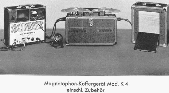
The K4 model is furnished with separate amplifier, and loudspeaker cases. The amplifier is of low power output, a single pentrode tube being used to operate the loudspeaker. Four inputs are provided for signal sources. These enable various input impedances and levels to be matched to the amplifier. A good quality moving coil, dural diaphragm dynamic microphone is furnished and is carried in a compartment in the amplifier case.
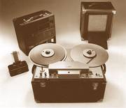
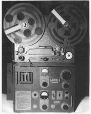
Figure 7 shows a complete K4 machine assembled, ready for operation and Figure 8 is the schematic of the playback preamplifisr, showing the equalization circuits.
Figures 10 and 11, in the section describing the RF7 R2h Zwillingsgeraete, give excellent views of the mechanism, which is virtually identical in the K4 and Zwillingsgeraete.
- Fig 6 oder 7 - Die Frontansicht des AEG K4 (also nicht K2 und nicht K3)

.
Magnetophon RPF R 2h Zwillingsgeraete
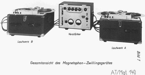
- Zwei AEG K4 Laufwerke gekoppelt für überlappenden Endlosbetrieb

In Germany the telephone and telegraph facilities are provided by the Government Ministry known as the "Reichspost". A number of machines were manufactured for recording purposes to provide special features not available in the normal K4 model, but which were required by this organization.
.

One of these machines is illustrated in Figure 9. It is attractively finished in the standard grey of the Peichspost apparatus, while the machines are essentially the seme as those of the K4, the amplifying equipment is entirely contained in the "Verstaerker" unit.
The compartment at the rear is given over to a series of relays and DC power supply beneath the dial and feeler finger seen in Figure 10. With the added relays and feeler this machine may be remotely started and stopped, switched to the second machine at the end of a reel of tape, and left in a standby condition with the tape drive motor running ("Tonrolle" shaft running) but without the tubber roller engaged (Gummiandruchrolle) so that the tape may be run only when an "incoming" signal is received.
Other desirable features are such things as automatic contacts which stop the machine immediately should the tape break and an alarm bell built into each machine for warning of the running out of film.
.

Figure II shows the interior of the mechanism with the relay and feeler cassette removed. This cassette space on top (hier imBild abgeschnitten) is that normally allotted to the preamplifier in the K4.
In the Zwillingsgerate the pre-magnetization current meter is located to the right of the amplifier panel instead of on the panel of the mechanism as in the K4.
The meter to the left is a volume indicator. The amplifier is designed to work from a telephone line and into a line on playback. Input and output impedances are therefore arranged for 600 ohms. The playback level is only 2.0 Nepers maximum which is not enough to drive a loudspeaker but is overly sufficient for feeding a telephone line.
The frequency range of this apparatus is limited by a band pass filter to within the band of 300 to 2700 cycles, within 3db. The device is thus seen to be one designed strictly for telephone service.
.
K5 Magnetophon
The Information on this equipment is incomplete. It is known that this is a permanent installation used by the Broadcasting stations and is now fitted for supersonic operation, in installation consists of two console-mounted mechanisms almost identical to the K4 without a preamplifier with recording, erasing and playback circuits rack-mounted in panel form nearby.
It is believed that this equipment was first produced as a high-grade DC set for limited use in broadcasting, and was later modified by the Reichs-Rundfunk Gesellschaft (RRG = German Broadcasting System) for supersonic operation.
Limited information on this set indicates that the first production was carried out by the broadcasting system, and later, AEG took over production. This set is said to have been produced in 1942, which is four years after the K7 and three years after the K6. It is therefore probable that the date refers to the time when AEG began production.
Anmerkung : Das mit den obengenannten Produktionsdaten ist sehr vage.
The only circuit available is that of the playback preamplifier. This is given in Figure 12. It is noted that this preamplifier, to minimize tube noise, uses an input transformer ratio of 62 to 1 from the pickup coil to the grid of the first tube, and omits the equalizing circuit previously used before the tube, so that it operates at the highest possible signal level.
Two resonant equalizer boost circuits and a simple RC circuit are used between the stages, and a low-pass filter is used in the output stage cutting off at 15.000 cycles to prevent any possible hetradyning with the supersonics used in recording and erasing.
K6 Magnetophon
( Note : It is possible that this equipment is referred to as R6 or some other nomenclature, as it is a portable set).
Information on this set is also incomplete. It is knovvn to be a battery-operated portable set, intended for mobile recording of news events, etc, in broadcasting service. A circuit of the playback preamplifier, the only schematic available on this set, is shown in Figure 13, and Figure 14 gives the response characteristics.
It appears that this equipment used D.C. erasing and recording. It was produced by AEG in 1939. The standard military tube, RV 12 P 2000, is used in this set, and once again, to secure quiet operation, all equalization is placed after the input stage, with the exception of a condenser across the input transformer secondary, to give a slight boost at 5.000 cycles, prior to a rather sharp cutoff.
K7 Magnetophon (verbessertes AEG K4)
This is the equipment currently produced by AEG and in service at broadcasting stations throughout Germany. It is the opinion of the author that, all factors considered, this system provides the finest commercial recording facilities in existence for broadcasting and similar applications. Important features are the simplicity of the recording technique, the excellent frequency and volume range of the equipment and the advantages offered by the unique plastic tape recording material.
Überschwengliche Lobeshymnen aus den USA von 1945
As has been previously noted, recording technique is extremely simple. The principle considerations are to equalize properly, and to watch the volume level. Unlike other systems, however, brief over-modulation has no serious consequences, as it causes a gradual increase in distortion, and considerable over-modulation can be tolerated before distortion becomes objectionable.
In this system there is no equivalent of the crossover encountered in disc recording, or the light valve clash found in film recording. The absence of moving parts in the audio system simplifies adjustment problems. Furthermore, in event of a mistake in recording, it is only necessary to erase and repeat the unsatisfactory portion, and no tape need be lost.
A further advantage is that the recording is ready for immediate playback without further processing, and the same tape can be recused an unlimited number of times by erasing and re-recordings.
The K7 system as installed in broadcasting service is capable of a frequency range of 25 to 10.000 cps, with a volume range of as much as 80db under good conditions. This performance is believed to be superior to that of any system in commercial use in the US.
.
Eine Vielzahl von Vorzügen (gegenüber der Platte)
Furthermore, a number of advantages are presented by the use of plastic tape for recording. This is a relatively inexpensive material in comparison with steel wire, steel tape, film, or discs.
The recording does not appear to deteriorate with age, some of the early tapes seem to become brittle after several years storage, but it is believed that the later materials do not suffer from this trouble.
The tape is readily cut and spliced with scissors and fast-drying cement (gemeint ist sicher der "Kleber"), and the resultant splice (die Schnittstelle) is inaudiable in playing.
Non-magnetic leaders are available on which titles and data can be written for reference. The extreme thinness of the tape, and the moderate speed at which it is run allow about 22 minutes playing time from a lightweight roll some ten inches in diameter. The roll is easily handled, occupies small space, and may be shipped without danger of breakage. It is not damaged by dust, and the recent tape materials are not inflamable.
.
Die Besonderheiten des AEG K7 zu den Vorläufern
Thus, magnetic recording processes as practiced in the K7 Magnetophon would seem worthly of closest investigation with e view to "widespread use in the States (gemeint sind dei USA).
The historical background of this model is not clear. Indications are that this was introduced by AEG as an improved version of the K5 permanent installation for broadcasting, about 1938. At that tine it was a D.C. erasing system, of somewhat wider range and better signal-to-noisc ratio than the previous equipments.
Circuits of the D.C. model recording equalizer are available, and are given in figure 15. It seems, however, that this system as well as the K5 were modified by Reichs-Rundfunk personnel for supersonic operation, and the revised system was put into production by AEG in 1942.
The circuit of the recording amplifier, eraser, and "pre-magnetozation" oscillator used in the revised set are shown in Figure 16. The nomenclature, V7b, supports the belief that this is a replacement of the D.C. recording equalizer.
A circuit of the playback preamplifier V7 is included, and this bears the dato 1938 (Fig 18) suggesting that it is the one used with the D.C. equipment originally introduced by AEG. Response curves of the amplifier show a performance quite adequate for the high-quality equipment, but it is possible that the previously described V5 preamplifier of the K5 Megnetophon is used with the revised set in broadcast service, since it fits the same panel, and was developed by the Reichs-Rundfunk personnel concurrently with the V7b recording amplifier.
The mechanical system of the K7 Magnetophon is almost identical to the basic chassis shown in Figures 10 and 11. Again the framework is shorter as the rear preamplifier chassis is omitted. Two of these mechanisms are console-mounted, with glass tops closing over each machine to make an almost silent installation. The associated electrical circuits are reck and panel mounted nearby.
Etwas über die HF Vormagnetisierung
The principles of supersonic erasing and recording were discussed in an earlier section of this report. There are some points of interest in the circuits of the erasing and recording amplifier, in Figure 16.
The three tubes, type EL 11 are 6 watt tetrodes equivalents to the 6V6. The erasing oscillator feeds the coil through a 4:1 step-down transformer, with a condenser used to series-resonate the head.
The frequency is about 35 to 40 KC and it is not critical. The recording oscillator, operating at 80 to 100 KC, is coupled to the recording coil throug a small condenser, and a simple parallel-resonant-filter is used to keep appreciable high frequency current out of the audio output transformer.
The oscillator frequency is variable over a small range to tune to this filter. The screen voltage is also adjustable to control the amplitude of supersonic's, which is stated to have an optimum value for best signal-to-noise ratio.
The audio amplifier is designed to take the output from any flat-response low-impedence source, equalize it, and feed the recording coil. The tube, operating as a pentode, approaches constant current feed of the coil. This is equivalent to increasing the feed voltage proportionately with frequency, since the coil is an inductive load. In addition to this, the transformer input to the stage is bridged with a resonant boost tunel to 9 KC, used to compensate for slit loss. This is variable, and is capable of increasing the recording current at 9 KC by as much as 12db over the 1 KC reference value.
The curves of this amplifier are given in Figure ??. The amplifier circuit includes a built-in meter, with rectifier and three-position switch to check erasing current, recording current and provide monitoring of the audio level during recording.
This office had modified a K4 Magnetophon for supersonic operation to substantiate the results achieved with this system and investigate the effect of various factors. The modification is relatively simple and so improves results that it is worth performing on any set intended for use where quality is a consideration.
The K4 head assembly was modified by substituting for the D.C. erasing coil a modified recording as playback head. This was prepared by re-winding the coils with large (approximately Nr. 22) wire to enable feeding at high frequency, and by inserting a brass shim in the slit to give a gap of about 1.5 millimeters. This coil was mounted on an improvised bracket in place of the D.C. coil.
It is possible that further investigation would indicate an optimum amount. It is certaint, however, that the current used for recording is only a fraction of that used in erasing.
Results achieved with this setup were extremely encouraging. Tope noise was reduced to the point, where noise originating in the preamplifier was the limiting factor. Our measurements indicated that a volume range of about 60 db was achieved.
VI - DESCRIPTION OF TONSCHREIBER SERIES :
The "Tonschreibers" are military versions of the Megnetophon. They use the same magnetic tape, and the erasing, recording and playback heads are almost identical. The essential differences are found in the mechanisms and the packaging. The Tonschreibers were used for front-line recording of events for broadcasting, and for intercept of telephone, radio and telegraphy. The Tonschreiber was especially adapted for the intercept role.
In common with most German equipment this series is heavily built by American standards. It would appear that re-engineering could reduce the complexity and weight considerably, but it must be concluded, that the Germans have produced a line of practical recording equipments which should fulfill service requirements.
Tonschreiber b
- Tonschreiber b

The Tonschreiber b was designed for use in intercept and de-coding service, where some source of alternating current (220V) was available.
To facilitate the intercept end deciphering application, it was considered desirable to produce a recorder in which the tape speed could be maintained positively at any value between 9 and 120 centimeters per second.
To do thus, it became necesarry to rely on the stability of a variable audio oscillator to provide locking tone for a phonic wheel motor. This motor is on the shaft of the tape propulsion drive but does not provide the running torgue which is furnished by a motor operated from 50 cycle mains through a transformer.
Changing the frequency of the oscillator by means of a multiposition tap switch is accomplished by a knob on the control panel which changes the taps on the 50 cycle transformer as well. This changes the excitation of the mains motor so that it tends to run the drive at a speed approximated that at which it will be held by the synchronous phonic wheels. To provide the phonic wheel with sufficient locking energy the oscilJator is amplified by a push-pull stage using the German LS-50 tubes. All this construction makes a heavy unit and one far more bulky than the American wire recorder or Amertype" machine, although the available choice of speeds may be anywhere within the above limits, a ratio of 13 to I in accurately maintained tape velocities, Flyball governors or variable friction drives cannot produce such constancy, of course.
Die Laufwerkfunktionen mit allen Tricks
The take-up spool is not driven from either of these motors.A third motor operated from mains supply provides, through friction drive, a means of taking up the tape on either the receiving reel or the rewind. The involved mechanical linkage and switching system applies power to the third motor only and engages it to the rewind spindle when the control lever seen at the bottom of the machine is pushed to the left, when pushed to the right from the neutral position the lever applies power to the same motor which is now coupled to the take-up spindle. At the same time power is applied to the tape propulsion motor and to the oscillator amplifier where it causes the phonic wheel to lock the latter motor into constant speed.
A rubber idler is, at the same time, brought into contact with the tape propulsion motor spindle. The tape running between the two is therefore driven at constant speed. To record, a second lever must be operated, but this can only be done at the same time the control lever is moved from neutral to "forward" position.
This procludes involuntary erasing of the tape. The lever springs to normal when the main-control is restored to neutral. A tachometer indicates the true running speed of the tape. A fourth motor is used to drive a playback rescanner which is made in the form of a small cylinder around which the tape must slip "en route" to the take-up spool.
This cylinder is rotated by the motor and as the tape is driven past it, the rescanner, which contains four pick-up coils 90 degrees apart, scans the tape in short segments but at a velocity higher than the actual velocity of the tape itself. Since some of these four coils is in contact with the tape at any instant, the tape is continually reproduced.
Die variable Geschwindigkeit für Verschlüsselungen
The rate of reproduction of information contained on the tape is a function of the true running speed of the tape, but the pitch is a function of the difference in speed of the tape and the scanning coil. Thus the tape may be slowed down to enable code recordings to be deciphered, but the pitch can be retained to enable this to be readily accomplished.
Similarly speech may be slowed down without lowering the pitch of the speakers voice. This enables transcriptions to be made directly by typewriter or longhand.
With its four motors and special features the mechanical unit weighs 76 pounds. The drive oscillator with its IS-50 amplifiers and audio recording and playback amplifiers are in a second box weighing 85 pounds.A third box contains a spare recording head and films.
The quality of recording obtainable is not very good. The signal to noise ratio is poor, due to tape noise and induction into the audio circuits of the locking oscillator tone. It might well be used for code or speech.
Use of the machine for delayed broadcast applications in the military service, similar to those uses to which the "Armour" wire recorder has been put by our own forces would not be advised. Of considerable annoyance is the induction due to the phonic wheel synchronizing tone since this is high enough in pitch to produce an objectionable "whine" in the loudspeaker or headphones.
The mechanical control applies brakes to the reels when the mechanism is stopped. If not properly operated these may not act fast enough. The result is that the tape is allowed to form a slack loop after power is removed and before the brakes are applied. This usually results in a broken tape. Repair, while readily accomplished with quick drying cement, is annoying and may cause serious delays and lost recording time.
It may be concluded that this machine is fairly difficult to operate and that training may be required to essure satisfactory results. It may be compared to a l6mm sound projector in difficulty of threading and operating.
.
Tonschreiber b 1
While this is essentially the same device as Tonschreiber b, it is known that one minor difference is the employment of an output transformer between the LS50 tubes and phonic wheel motor. The model b was manufactured with high impedance push-pull motor windings insulated to withstand plate plus signal potential since they were connected directly to the tubes. The change from model b to b 1 was apparently made sometime in 1942-43 no doubt, to insulation break-down.
A more detailed description of the circuits of this equipment may be found in EEIS report, Number EEIS II-I2, which should be obtainable from Intelligence Branch, Office of the Chief Signal Officer, War Department, Washington, D.C. A picture of the set in operating position is given in Figure 20.
Tonschreiber c
This is a small apparatus intended for portable use in the field where minimum weight is important and power may not be available. The "C is really two separate machines, as seen in Figure 4. The Sc (A) unit, (A^ufnahme or record)is the recorder and does not provide playback facilities. It is completly self contained in a box 22.5 x 34.0 x 22.3cm, weighing 26,4 pounds.
.

.
A second box containing 36 reels is 20,2 x 34.0 x 20,2 cm in size and weighs 21 pounds. The recrder itself employs no amplifier and contains a flashlight battery which provides current for a telephone microphone normally carried in a compartment at the rear of the case.
Terminals provide recording facilities for radio or other external source. The tape is propelled by spring motor at 12 centimeters per second. This enables intelligible speech recording and completely satisfactory recording of code tonos under 1.500 cycles.
2.000 cycles can be recorded and reproduced at this tape speed, but not in the presence of strong signals of lower frequency. It must be realized that very little energy is required in magnetic recording. It is thus possible to employ the microphone or external low level signals directly without the use of a recording amplifier.
A DC component must be provided in the recording coil whenever recordings are made. This is obtained from the self contained battery. It is therefore essential that the battery be installed even though the microphone may not be employed. In using the Sc(a)unit, the film is unwound by the spring drive at a constant speed controlled by a flybell governor.
After the tape passes through a drive roller it is wund on a take-up-spool which is coupled by a friction clutch to the spring mechanism. It can be seen that even in this simple machine pains are taken to assure constant linear speech of the tape.
This is in sharp contrast to the American wire recorder wherein constant angular speed of the take-up-spool only is attempted. This results in the linear wire speed being a function of instantaneous diameter of the spool.
Furthermore no attempt is made in the American (wire) machine to stabilize the speed of the take-up-spool. A rubber belt is used to drive the take-up. Such a drive is an almost certain way of introducing speed oscillations in the driven system. This, of course, is one of the principle reasons why the American wire recorder is completely unsuitable for music.
When a tape is recorded completely, it must be placed on the second machine of the Sc Tonschreiber. This is, as seen in the illustration, of approximately the same dimensions as the Sc (A), but is electrically driven from batteries contained in another box.
This machine, complement of time Sc (A) is called the Sc (W), (Wiedergabe or playback). It contains a three stage amplifier, operated from the batteries which provide motor power and erasing current so that a tape may be prepared for the Sc (A) machine after it is completely transcribed.
(Seite 27 ist fast nicht zu lesen)
The Sc Tonschreiber is a good piece of German construction solidly built and rugged enough to withstand very rough treatment - hier fehlt ein ganzer Satz -and it is unsuitable for music recording because of its limited frequency response and signal to noise ratio.
.
Tonschreiber d
To provide a larger machine with both recording and playback facilities yet operated from a 12 Volt DC source, this machine was developed. It is of about the same dimensions as the mechanism unit of Tonschreiber b, full details are not known, but it provides a single tape speed and is not fitted with the unique pitch restored of the Tonschreiber b.
Since phonic wheels drive is not employed; no high power oscillator amplifier is required and the machine is correspondingly much lighter in weight. The associated electrical circuits are contained in the case with the running mechanism. A separate case contains the nickel cadmium batteries and a third case contains spares and approximately 20 reels of tape. This equipment uses a plug-in head assembly identical with the Tonschreiber b.
Appendix A
THE MAGNETOPHON METHOD
This appendix is a translation of an article by Professor Dr. Eggerth and Dr. Lübeck of the I.G. Farben plant, which produced the tape used in this system.
The article discusses some phases of the development history of this system, and presents a summary of its advantages and uses.
A short discussion is given on the materials and manufacturing processes used in making the tapes. It is considered by this office that the Luvitherm tape, described in the last section, is considerably superior to the earlier types. The authors of this article may be regarded as authorities on this subject.
- Anmerkung : Leider wird über das Datum dieses ehemals deutschen Artikels keine Angabe gemacht. Ich vermute, er stammt aus 1942 oder noch früher, jedenfalls von vor der Kapitulation von Stalingrad Feb. 1943.
.
I.G.Farben Industrie AG - Camera Plant
"THE MAGNETOPHON METHOD"
.
- In diesem letzten aus dem Deutschen ins Englische übersetzten Abschnitt geht es etwas zu wie in "Kraut und Rüben" - also alles ziemlich durcheinander.
.
I) Survey.

The magnetophon method is based on essentially the same physical process as the magnetic steel wire or steel tape method. In both cases the currents coming from the microphone are amplified and sent through magnet coils; the sound carrier, which can be magnetised, is carried in front of these coils at an even speed.
In both cases the record may be listened to during recording, and as often afterwards as desired. In both cases the record may be erased any number of times and may be completely or partially replaced by another. Compared to the steel sound carriers, the magnetophon tape has the following advantages :
.
- 1) The magnetophon tape is lighter than steel tape for the same playing time.
- 2) The magnetcphon tape is cheaper then the steel sound carriers.
.
Hier fehlt im Original ein (kleiner) Absatz auf Text-Seite 28. (Die Seite ist extrem unleserlich.) und ended mit "......... generally applied."
AEG undertook the construction and mass production of the apparaturs; I.G. the fabrication of the tape. At AEG (in Berlin) the following worked on the project :
.
- Dr. Schlepelmann,
- D. C. Schüller, (war as nicht Eduard Schüller)
- Dr. Lübeck and associates
at the I.G. works in Ludwigshafen:
.
- D. Mathias, (korrekt : Dr. Friedrich Matthias)
- D. J. Friedmann,
- Dr. Brill. and associates;
at the Film works in Wolfen:
- Prof. Dr. Eggert,
- Dr. Mertelsmann,
- Dr. Gladborn,
- D.J. Nissen,
- Dr. Wendt,
- Dr. Wutke and associates.
During the tests of the method for broadcast transmission at the Reichsrundfunkgesellschaft (Broadcasting Society of the Reich in Berlin) Dr. von Braunmühl and Dr. Weber 1941 found an essential improvement in the method which gave a "unbelievable" (das war nicht leserlich) of lowering in the back ground noise level. This "übertraf" considarably the extent of the volume of the record (gemeint ist die Schellack-Aufnahme). At this time the magnetophon method became the topmost of all sound recording methods.
On account of the growing demands from varied consumers, AEG and I.G.- decided, to create an independant branch establishment known as the Magnetophon Society. This company has been in Berlin since 1942. Dr. Schlepelmann and Dr. Mathias were appointed as managers. The Magnetophon Society transacted business with the consumers from this time but at the same time was in close contact with the patent firms.
The equipment was manufactured by AEG, Drontheimerstrasse, the I.G. Film factory Wolfen delivered the tape. In addition towards the end of 1942, AEG established another branch, the Tonband GmbH also at Berlin. While the Magnetophon GmbH the apparatus and original sound carriers, the Tonband GmbH is concerned with the production, reproduction and sales of Magnetophon tape records, an enterprise analogous to the manufacturer of phonograph records. At present, it supplies sound tape and copies. Dr. Lübeck is the managing director.
- Anmerkung : Die obigen Absätze waren natürlich alle nur noch reine patriotische Theorie während der Endphase des 2. Weltkrieges, als die Fabriken der I.G.Farben fast alle schon in Schutt und Asche lagen und nur noch - wenn überhaupt - fürs Militär produziert wurde.
.
3) The Megnetophon Apparatus :
According to its use, the apparatus has been built in different models :
.
- 1) The simplest apparatus is similar to a suitcase, easy to carry, so that it may be taken about by a person on foot for purposes of reporting.
- 2) The dictation machine is more elaborate; it may also be used to record conferences. In addition to the high speed reverse mechanism on all equipments, there is also a remote control device, provision for telephone connection, etc.
- 3) The magnetophon allows essentially better recording quality.
- 4) The magnetophon tape is worn less by the apparatus.
- 5) The magnetophon tape may be cut at will, end easily spliced together like motion picture film, so that records from different rolls may easily be fitted together. At the same time, the Magnetophon tape is tough enough to resist easy breakage.
- 6) Notes may be written on the tape designating the whole roll or certain parts of it.
.
On account of these advantages, the following fields of use are open to the Magnetophon method :
.
- 1) Dictation
- 2) Records of conferences, trials, broadcastings, etc,
- 3) Use for broadcast transmissions (the method has already widely replaced older techniques in German broadcasting).
- 4) Use as a tape phonograph for amateur reproduction.
- 5) It is clear that the method may be used wherever mechanical-electric or photographic sound recording has been used in the past.
.
There is no doubt that the magnetophon method is decidedly at the head of all sound recording methods; at present microphones, amplifiers and loudspeakers are not capable of completely reproducing the frequency range and dynamic response of the magnetophon.
This was not the case to the same extent with mechanical and photographic methods, compared with the latter recording process, this system has a maximum of simplicity.
2) Historical Development :
The basic idea of the method was originated by Mr. Poulsen (1900). A certain Mr. Pfleumer, private person at Dresden, received a patent in 1930 on the idea: to use a paper or cellulose tape on which iron dust is spread by means of a cement, instead of the steel material previously used. This development was taken up by AEG, Berlin, and I.G. Farben, Frankfurt/Main, soon after with the intention of developing a sound recording and reproducing method which could be :
3) For broadcasting purposes, a number of equipments with especially high quality were manufactured. The frequency range of these equipments extends from 25 to 10.000 c/s, the dynamic range to 65 or 70db, and can be brought to 80db, Distortion is less than 2%.
4) An amateur apparatus was planned which was to be much simpler, and similar to the Reporter equipment, and was to be used as a phonograph in private and public houses, etc. It was to be used only for reproduction, not for recording.
In addition to the above, AEG manufeatured three special types for the Wehrmacht (German Military) :
5) The trench equipment (Tonschreiber C) a reporter's sound recorder of very small dimensions with a clockwork drive,
6) The haversack apparatus (Tonschreiber D) a heavier type, also used for reporting purposes,
7) The Tonschreiber B, a special apparatus with a particularly constant tape speed adjustable from 10 to 125 cm/sec (necessary for deciphering high speed telegraphy). In addition, this device permits speech to be slowed down 2 to 5 times without lowering the sound level. The language remains easy to understand. This is of use for the convenient transcription of dictation, speeches, etc.
Allen Magnetophonen gemeinsam ist :
Except for the above mentioned differences in construction, all Magnetophons have the following in common :
.
- 1) amplifier
- 2) Motor drive operating the wind and rewind of the tape, The very precise tape speeds are 77cm/sec for high precision equipment, 25cm/sec for dictation equipment, and 10cm/sec for the trench equipment.
- 3) The magnet heads : In recording, the magnetophon tape slides across the erasing head, which magnetizes the tape up to its highest value of magnetisation, and so wipes out all previous records.
.
Next to it, and in the same movement, the tape passes the recording head. It contains two coils placed around ring shaped magnets, through which the amplified microphone currents flow.
The gap between poles is about 0.02mm and is slightly convex so that the tape can slide across the recording head in close contact.
The stray magnetic field formed between the poles is directly absorbed by the active layer of the tape which is megnetic, and leaves in it a residual magnetism, which is distributed according to the frequency amplitude of the signal.
Manche Seiten sind unlesbar
Hier als Beispiel der nächste Absatz, der auch mit den Augen und dem Gehirn nicht zu entziffern war :
"According to the u3G that .is t: be rt-de of the record and ^ho uuelifcy demanded, '-he .¦ ."i'n of ti'.o rocordor.g oeca re'.'-ei vo a direct or hooh f^. vuen;y 3.J torr.oJ. oog o-rrer.t or.'-o wh.i :.h ohe mod'jlahj -;i voltage is svperpc.oeJ- Reproduction nay be executed 'in the same opera ;ion r as J;he erasing and recording. iy.it the reoyrd '.ng head can he p'uj.tohed oi;'f and the i\r> ;.ening A'--fr6 ocn/.ected to a Joodepeaker through an amr J If ie i :
The receiving head, in which the magnetic fields produced by the tape induce alternating current, correspond in freguency and amplitude to the record currents, is built in the same way as the recording head.
5 The Magnetic Tape


If the method using the idea of Mr. Pfleuner was to compete with the existing methodsof recording, it was understood from the start, that the idea needed a ????? working through. This took about 10 years.
The tape, as used at present, has a width of 6mm and a thickness of 0.04 to 0.05 mm, and is as a rule, prepared in spoils of 500 (stimmt das ?) meters.
This lengt plays for about 20 minutes on the fast running equipmentand about 70 minutes on the slow. The spools have the generic appearance and diameter of thick phonograph records, and have a plastic hub with a hole which fits onto the plate of the equipment.
The active layer, 0,01 to 0,02mm, is supported by a cellulose acetate film. The active layer consists of 90% Magnetit and 10% cement. The supporting tape and Magnetit layer are produced in one operation and from batches of material large enough to manufacture 100 rolls.
The Mmagnetit is produced in a wet process by a hot oxydizing precipitition of an iron-II sulfate solution. The precipitate is washed, dried and made into powder, heated if necessary, and very thoroughly nixed with the cementing agent in a ball-mill.
.
Weitere Tape Details aus diesen deutschen Quellen

The grain size when lying flat is about 0.002mm, and is controlled microscopically and by analysis of sediment. The homogeneity of the mixture and the thickness of the active layer (the optimum thickness is found experimentally) are of great importance.
The finished tape is repeatedly tested for tensile strength sensitivity, frequency response, distortion, erasibility, attenuation and dynamic range.
In addition to the cellulose acetate, tapes of Luvitherm were manufactured at Ludwigshaven, which so as to differentiate them from the first type called C-tapes, were marked with the letter L.
The principal difference, compared to the C-tape is, that instead of using a supporting film, the magnetit is directly imbedded in the Luvitherm layer, so that the tapes consist of only one layer. Practical experience has shown that this tape has a somewhat higher resistance to breaking.
Both types of tapes can be reproduced up to 10.000 times without loss of quality,
Prof. Dr. Eggerth, Dr. Lübeck (Datum des originalen Artikels unbekannt)
DISTRIBUTION (die Verteiler-Liste von 1945)
OCSigO, SPSOI-2, War Dept., Washington 25 D.C. .......................... (5)
TL Division, Signal Section, U.K. Base, APO 413 ................................ (1)
ADRO, T-2 Section, Wright Field, Dayton, Ohio .................................. (2)
American Embassy Mil Attache (Sig C) London, Attn: Major Walter ... (1)
War/Office,M.I.8, Hotel Victoria, London, England ............................. (2)
Canadian Military Hq. Attn: SD 10, 2 Cockspur St., London, S.W.I . . . (1)
D.S.D.9, Admiralty, Whitehall, London, S.W.I. .................................... (1)
OSRD Hereford House, 117 Park St., London, W ...................l............ (1)
A.D.I. (Science), Air Ministry, Whitehall, London, S.W.I. ..................... (2)
A.I.2.G. Air Ministry, Whitehall, London, S,W.l. ................................... (2)
U.S. Navy, Readiness Div. 8 Grosvenor Square, London, England ..... (1)
Nav. Adv, 0 Mil Govt for Ger (U.S.) c/o Fleet P 0, U.S. Navy ................ (1)
Chief Field Information Agency, Technical, c/o G-2 USF3T APO 757 .... (1)